

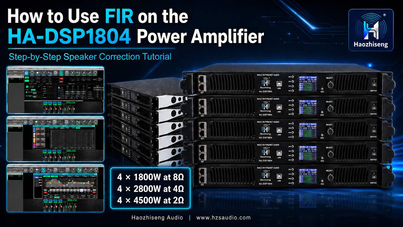
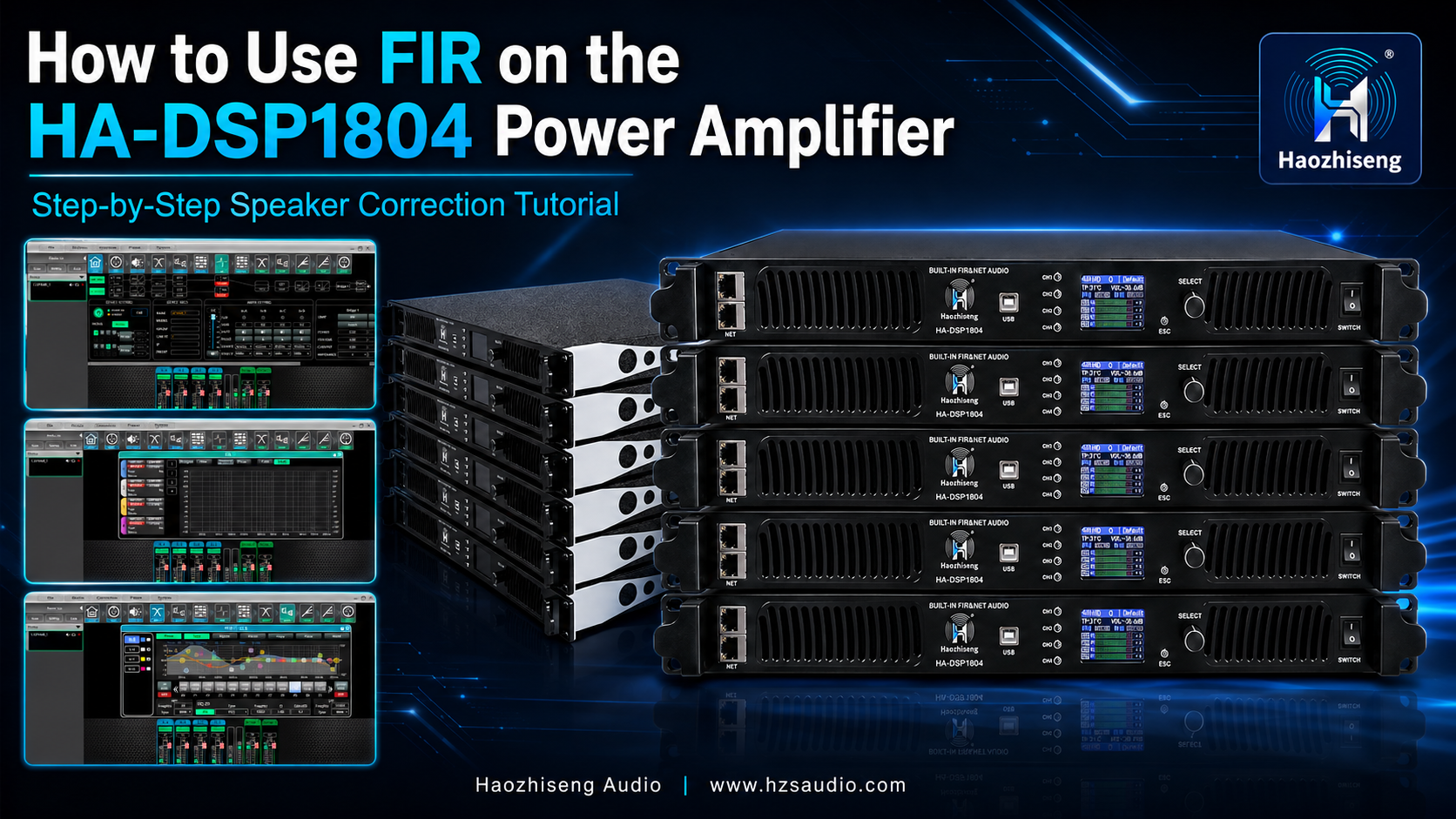
How to Use FIR on the HA-DSP1804 Power Amplifier: Step-by-Step Speaker Correction Tutorial
Modern professional sound systems require more than high amplifier power. Accurate loudspeaker processing, predictable phase response and consistent system performance are equally important.
The Haozhiseng Audio HA-DSP1804 combines four-channel high-power amplification, advanced DSP processing with FIR filtering, a PFC wide-voltage power supply and Dante network audio integration in one professional platform.
In this tutorial, we will explain how to:
- Measure a loudspeaker’s original response using Smaart
- Import the measurement into FIR Designer
- Apply phase correction
- Apply magnitude correction
- Generate an FIR filter
- Activate the FIR filter on the correct channel
- Compare the corrected and uncorrected results
Watch the HA-DSP1804 FIR Video Tutorial
For a visual demonstration of the complete workflow, watch our product tutorial on YouTube:
Watch the HA-DSP1804 FIR Software Tutorial on YouTube
You can follow the video while using the written instructions below as a step-by-step reference.
What Is an FIR Filter?
FIR stands for Finite Impulse Response. In a professional loudspeaker system, FIR filtering can be used to modify both the magnitude and phase response of a loudspeaker.
Traditional IIR filters are effective for crossover, equalization and system tuning, but magnitude and phase are normally linked. FIR processing provides greater control over phase and frequency-response correction, making it possible to create a more linear and predictable loudspeaker response.
When correctly designed, an FIR filter can help:
- Improve phase response
- Flatten the frequency response
- Improve crossover alignment
- Increase consistency between loudspeaker components
- Improve transient accuracy
- Create manufacturer presets for different loudspeaker models
- Provide more precise system tuning
However, FIR processing cannot repair mechanical damage, an incorrectly designed enclosure, severe room reflections or a poor-quality measurement. The final result still depends on the loudspeaker, measurement conditions and filter settings.
What You Need Before Starting
Prepare the following equipment and software before creating the FIR filter:
- Haozhiseng Audio HA-DSP1804 amplifier
- Computer with the HA-DSP1804 control software
- Smaart measurement software
- FIR Designer
- Calibrated measurement microphone
- Professional audio interface
- Suitable microphone stand
- Test signal source
- Correct network or USB control connection
- Loudspeaker connected to the correct amplifier channel
FIR Designer supports loudspeaker-measurement import, phase adjustment, magnitude correction and FIR-filter generation as part of its loudspeaker-processing workflow. It can also work with Smaart measurement data. For detailed third-party software information, refer to the official FIR Designer website.
Important Preparation
Before beginning:
- Save a backup of the current amplifier preset.
- Confirm that the loudspeaker is connected to the correct output channel.
- Check the loudspeaker impedance and safe operating power.
- Confirm the DSP sample rate and supported FIR tap length.
- Temporarily bypass any unnecessary EQ that could affect the raw measurement.
- Keep essential driver-protection filters active when measuring individual components.
- Use a stable microphone position and minimize environmental noise.
- Begin at a safe test level before increasing the measurement volume.
Never measure a high-frequency driver without the required protective high-pass filter.
HA-DSP1804 FIR Correction Workflow
Step 1: Measure the Loudspeaker’s Raw Response with Smaart
The first step is to capture an accurate measurement of the loudspeaker before FIR correction.
Position the measurement microphone in front of the loudspeaker at an appropriate distance. The microphone should be placed on the loudspeaker’s main acoustic axis unless your test procedure requires a different position.
Use Smaart to measure the loudspeaker’s original:
- Magnitude response
- Phase response
- Impulse response
- Time alignment
- Measurement coherence
Make sure the measurement has a reliable time reference. Incorrect delay alignment can create misleading phase information and produce an unsuitable FIR filter.
The environment should be as quiet as possible. Reflections from floors, walls and ceilings may affect the result, particularly at lower frequencies. For product preset development, an anechoic chamber, outdoor measurement area or properly controlled test space is recommended.
Once the measurement is stable, save or export the raw response curve in a format compatible with FIR Designer.
Do not apply excessive smoothing. Too much smoothing may hide important response characteristics, while insufficient smoothing may cause the filter to follow insignificant measurement variations.
Step 2: Import the Raw Speaker Curve into FIR Designer
Open FIR Designer and import the loudspeaker’s raw measurement curve.
After importing the file, verify that:
- The frequency range is correct
- The magnitude response is displayed correctly
- The phase response is continuous and valid
- The measurement level is reasonable
- The impulse timing is properly aligned
- No incorrect delay offset is present
If the imported phase curve looks unstable or contains sudden rotations, return to Smaart and confirm the measurement delay, coherence and impulse-response timing.
A clean and repeatable measurement is essential. FIR Designer can only create a reliable correction filter from reliable measurement data.
Step 3: Set the Phase-Correction Frequency Range
Go to the phase-correction settings page in FIR Designer.
Select the frequency range over which phase correction should operate, and then enable the phase-correction function.
Do not automatically correct the entire available frequency range. Choose a correction range that matches the loudspeaker’s actual operating bandwidth and the reliability of the measurement.
For example:
- Avoid correcting frequencies below the loudspeaker’s useful low-frequency range.
- Avoid correcting high-frequency data with poor coherence.
- Do not force correction through a crossover region unless the measurement and target are correct.
- Use a controlled correction window to prevent unnecessary filter complexity.
The objective is not to create a visually perfect line at every frequency. The objective is to improve the loudspeaker’s useful response without introducing excessive latency, ringing or unstable correction.
Step 4: Select the Channel and FIR Tap Length
After setting the phase-correction range, select the output channel that corresponds to the loudspeaker being processed.
Next, choose the appropriate number of FIR taps.
The tap length affects:
- Low-frequency correction capability
- Frequency resolution
- Processing latency
- DSP resource usage
A higher number of taps can provide greater low-frequency resolution, but it may also increase system latency. The best setting depends on the loudspeaker, crossover frequency and intended application.
For stage monitors or applications where latency must remain very low, a shorter FIR filter may be preferred. For system tuning, fixed installations or linear-phase crossover applications, a longer filter may be suitable.
Always choose a tap length supported by the HA-DSP1804 and appropriate for the selected DSP channel.
Step 5: Generate the FIR Curve
After selecting the channel and tap length, click “Generate.”
The software will calculate the FIR filter using the imported loudspeaker measurement and the phase-correction settings.
Review the generated response before activating it. Check for:
- Excessive correction
- Unexpected gain increases
- Sharp or unnatural filter shapes
- Excessive phase manipulation
- Correction outside the loudspeaker’s usable frequency range
If the generated result appears unreasonable, do not apply it immediately. Recheck the original measurement, correction range and tap settings.
Step 6: Activate the FIR Filter
After the FIR curve has been generated and assigned to the correct channel, locate the “Bypass” control for that channel.
Disable “Bypass” to activate the FIR filter.
In other words:
- Bypass enabled: FIR processing is not active
- Bypass disabled: FIR processing is active
Confirm that the FIR filter is being applied to the intended amplifier output. Applying a filter to the wrong channel could produce incorrect frequency response or create a risk for the connected loudspeaker.
Begin listening at a safe level and verify that the loudspeaker is operating normally.
Step 7: Compare the Corrected and Uncorrected Phase Responses
After activating the FIR filter, compare the corrected response with the original response.
In our software display:
- The green curve represents the corrected response.
- The blue curve represents the uncorrected response.
The corrected phase curve should appear smoother and more linear through the selected correction range.
Do not judge the result only by the appearance of the graph. Repeat the measurement with Smaart to confirm the actual acoustic output of the loudspeaker.
The final evaluation should include:
- On-axis response
- Phase response
- Impulse response
- Crossover behavior
- Off-axis response
- Listening tests
- System latency
How to Apply Magnitude Correction
After correcting the phase response, the next step is to improve the magnitude response.
Step 8: Open the Magnitude Settings Page
Go to the magnitude-correction page in FIR Designer.
Set the frequency range in which magnitude correction will operate, and then enable the function.
Choose a realistic target response for the loudspeaker. A perfectly flat curve is not always the best target. Depending on the loudspeaker and application, a controlled high-frequency slope or application-specific voicing may produce a more natural result.
Step 9: Set Safe Correction Limits
Avoid applying excessive boost to deep response dips.
A narrow, deep cancellation may be caused by:
- Room reflections
- Cabinet diffraction
- Microphone position
- Driver interaction
- Crossover misalignment
- Acoustic cancellation
Adding a large amount of EQ boost may consume amplifier headroom without solving the acoustic problem. It could also increase driver excursion and thermal stress.
Use correction limits and prioritize broad, repeatable response characteristics rather than narrow measurement anomalies.
Step 10: Regenerate the FIR Curve
After setting the magnitude-correction range and target, regenerate the FIR curve.
The new FIR filter will now include both:
- Phase correction
- Magnitude correction
Review the predicted response and confirm that the correction remains within safe limits.
After generating the new curve, make sure the FIR Bypass function remains disabled for the corresponding channel.
Step 11: Measure and Verify the Final Result
Measure the loudspeaker again with Smaart after activating the new FIR filter.
Compare the new acoustic measurement with the original response.
After successful correction, both the magnitude and phase curves should appear flatter, smoother and more linear within the selected operating range.
Verification is essential because the predicted software response and the real acoustic response may not be identical.
The final correction should provide a practical improvement in:
- Frequency-response consistency
- Phase linearity
- Crossover integration
- System clarity
- Transient response
- Loudspeaker-to-loudspeaker consistency
Save the completed amplifier preset with a clear name that includes the loudspeaker model, channel assignment, sample rate and FIR version.
Common FIR Tuning Mistakes
Using an Unreliable Measurement
Poor coherence, incorrect microphone placement or an inaccurate delay reference can produce an incorrect FIR filter.
Always repeat the measurement and confirm that the response is consistent before creating the filter.
Correcting Too Wide a Frequency Range
Do not apply phase or magnitude correction outside the loudspeaker’s useful bandwidth. Limit correction to the frequency range where the measurement is reliable and the loudspeaker can operate safely.
Applying Too Much Boost
Large boosts reduce headroom and increase stress on the loudspeaker and amplifier. Deep acoustic cancellations should not normally be corrected with aggressive equalization.
Selecting the Wrong Channel
Always confirm the amplifier output channel before activating an FIR filter. Each filter must match the loudspeaker or driver connected to that channel.
Forgetting to Disable Bypass
Generating an FIR curve does not necessarily mean that it is active. Disable the corresponding Bypass control and confirm the status before evaluating the result.
Ignoring FIR Latency
Longer FIR filters can create additional latency. Consider the application before selecting the tap length, especially for stage monitoring, live instruments and low-latency performance systems.
Evaluating Only One Microphone Position
A correction based on one unusual microphone position may not represent the loudspeaker’s overall performance. For professional preset development, verify the result at several relevant positions.
Recommended Amplifier: Haozhiseng Audio HA-DSP1804
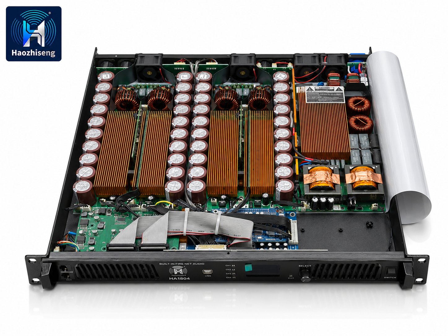
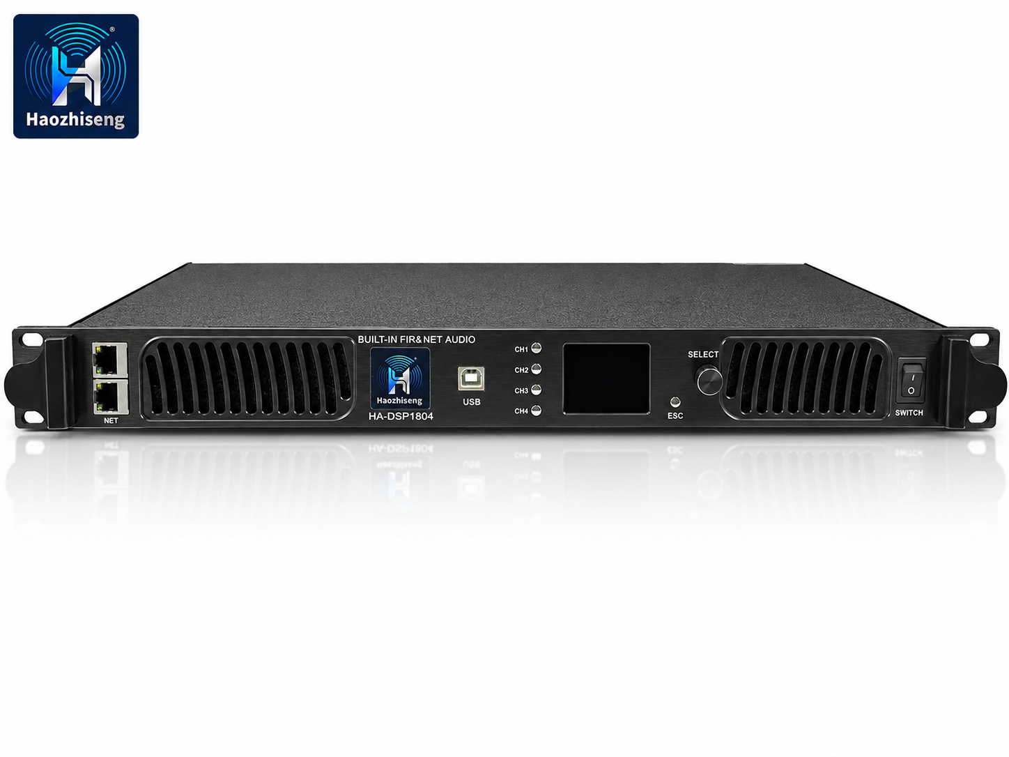
The HA-DSP1804 is a four-channel professional DSP power amplifier designed for touring, rental systems, line arrays, professional subwoofers, nightclubs, theaters, houses of worship and fixed installations.
It combines high-power amplification, advanced FIR processing, Dante network audio and wide-voltage PFC technology in a compact professional platform.
HA-DSP1804 Key Specifications
High-Power Four-Channel Output
- 4 × 1800W at 8Ω
- 4 × 2800W at 4Ω
- 4 × 4500W at 2Ω
The four-channel design can drive multiple full-range loudspeakers, line-array sections, stage monitors or high-power subwoofers from one amplifier.
90–260V Wide-Voltage Power Supply with PFC
The HA-DSP1804 features a 90–260V AC wide-voltage power supply with Power Factor Correction.
This provides important advantages for:
- International distributors
- Touring sound systems
- Rental companies
- Outdoor events
- Generator-powered systems
- Regions with fluctuating mains voltage
- Projects requiring one amplifier platform for different markets
PFC improves how the amplifier draws power from the AC supply, while wide-voltage capability allows it to operate across different regional voltage standards within its specified range.
Correct branch-circuit capacity, cable size, grounding and power distribution are still required, particularly when operating high-power systems at lower mains voltages.
Advanced DSP Processing with FIR
The integrated DSP platform provides powerful loudspeaker-management capabilities, including FIR processing for precise phase and magnitude correction.
This allows system engineers and loudspeaker manufacturers to create optimized presets for different cabinets and applications.
Dante Network Audio Integration
Dante network audio integration allows digital audio signals to be distributed through a standard network infrastructure.
This can simplify signal routing, reduce analog cabling and support flexible system design for touring and fixed-installation projects.
Easy Installation and Control
The HA-DSP1804 integrates amplification, DSP processing, FIR filtering and network audio in one system.
This reduces the number of separate devices required in the amplifier rack and makes installation, preset management and system control more convenient.
Why Choose the HA-DSP1804?
The HA-DSP1804 is especially suitable for customers who need:
- High output from a compact four-channel amplifier
- Stable 2Ω driving capability
- FIR-based loudspeaker correction
- Professional DSP system control
- Dante digital audio networking
- PFC wide-voltage operation
- Simplified amplifier-rack installation
- Preset creation for OEM or ODM loudspeaker systems
- Flexible use in touring and fixed installations
It is not simply a high-power amplifier. It is an integrated amplification and loudspeaker-management platform designed for modern professional sound systems.
Frequently Asked Questions
What is the difference between FIR and IIR filters?
IIR filters are efficient and widely used for EQ, crossovers and loudspeaker protection. FIR filters provide more independent control over magnitude and phase, but they require more DSP resources and may introduce additional latency.
Many professional systems use FIR and IIR processing together.
Does FIR automatically improve every loudspeaker?
No. FIR performance depends on accurate measurements, appropriate correction settings and the physical performance of the loudspeaker.
FIR cannot repair a damaged driver, eliminate all room reflections or correct severe acoustic cancellation.
How many FIR taps should I use?
The correct tap length depends on the required frequency resolution, correction range and acceptable latency.
Longer filters can improve low-frequency resolution but usually create more latency. Always use a tap length supported by the HA-DSP1804.
Should I correct the entire frequency range?
Usually not. Apply correction only within the loudspeaker’s useful operating bandwidth and where the measurement data is reliable.
Can FIR correction replace a properly designed crossover?
No. FIR is a powerful optimization tool, but the loudspeaker still requires correct driver selection, enclosure design, crossover planning, protection and acoustic measurement.
Why must the corrected response be measured again?
FIR Designer predicts the effect of the filter, but the actual loudspeaker, amplifier, room and measurement position determine the final acoustic result.
A new Smaart measurement confirms whether the correction works as intended.
Conclusion
FIR processing gives professional audio engineers greater control over loudspeaker magnitude and phase response, but successful correction begins with an accurate measurement and a controlled workflow.
The complete process is:
- Measure the raw loudspeaker response with Smaart.
- Import the measurement into FIR Designer.
- Set and enable the phase-correction range.
- Select the correct channel and FIR tap length.
- Generate the FIR curve.
- Disable Bypass to activate the filter.
- Compare the corrected and uncorrected responses.
- Set and enable magnitude correction.
- Regenerate the FIR curve.
- Measure the final acoustic result with Smaart.
When correctly configured, the green corrected curve should show a flatter and more linear magnitude and phase response than the blue uncorrected curve.
Combined with four-channel high-power output, 90–260V PFC technology, Dante network audio and advanced DSP processing, the Haozhiseng Audio HA-DSP1804 provides a powerful solution for modern professional loudspeaker systems.
Watch the complete tutorial:
HA-DSP1804 FIR Software Video Tutorial
Need more information about the HA-DSP1804 or help matching it with your loudspeaker system?
Please send us your loudspeaker model, quantity, impedance, rated power, wiring configuration and application. Our technical team can recommend a suitable amplifier and DSP configuration.
Haozhiseng Audio
Website: www.hzsaudio.com
Email: [email protected]
If this tutorial was helpful, share it with another audio engineer, loudspeaker manufacturer or system installer.
Leave a Reply